| View previous topic :: View next topic |
| Author |
Message |
phoskam
Snailer
Joined: 30 Oct 2007
Posts: 19
Location: Rossum, Netherlands
|
 Posted: Sat Dec 08, 2007 1:35 am Post subject: 4 cilinder tachometer on a visa engine Posted: Sat Dec 08, 2007 1:35 am Post subject: 4 cilinder tachometer on a visa engine |
 |
|
I've got a nascar style tachometer, wich can be set to 4,6 and 8 cilinder engines, but not at 2 cilinder.
Is there a way to modify the instrument itself or it's signal so it gives the right values ? |
|
| Back to top |
|
 |
Neil
Dropped

Joined: 03 Jul 2007
Posts: 285
Location: Cornwall UK
|
| Posted: Sat Dec 08, 2007 1:22 pm Post subject: Re: 4 cilinder tachometer on a visa engine |
|
|
| phoskam wrote: | I've got a nascar style tachometer, wich can be set to 4,6 and 8 cilinder engines, but not at 2 cilinder.
Is there a way to modify the instrument itself or it's signal so it gives the right values ? |
Hi phoskam,
I'm afraid i don't know a way of converting myself, but i can recommend these guys:
http://www.speedycables.com/calibration.htm
I used them to convert my GS tacho to work with 2 cylinders. Works out about 76 euros - not cheap!
_________________
www.international2cvfriends.com |
|
| Back to top |
|
|
Olli
Soviet-Finn Photoshoper
Joined: 25 May 2007
Posts: 2146
Location: Soviet-Finland
|
| Posted: Sat Dec 08, 2007 1:32 pm Post subject: |
|
|
One change is to use sensor on flywheel. Example BX have sensor on
crack what shows position of it. This sensor could give same information
for tacho than coil, but you can adjust it to show 4 pulses in one engine
round, like 4 cyl engine. Jasu knows much more about this.
-Olli
_________________
www.ollierkkila.com |
|
| Back to top |
|
|
Jasu
Dropped

Joined: 30 Sep 2007
Posts: 211
Location: Finland
|
| Posted: Sat Dec 08, 2007 2:12 pm Post subject: |
|
|
You can modify Your tachometer quite easily. Open the tacho, find resistors from switch where You can choose 4-6-8 cylinder -mode, find a resistor what is connected in switch for 6-cylinders and put adjustable resistor (trim pot, trimmer potentiometer) to place where that resistor was.
Then connect tacho to 2CV, put the switch to 4-cylinder, try to get idle for example 1000rpm, move switch to "modified 6-cylinder" and adjust trimmer to get tacho reading to 2000rpm, check the reading by changing the switch between 4- and 6-cylinders, and thats it.
You can also get "tacho-signal" from cheap battery charger, it gives not-so-good-dc, full bridge rectified dc in 100Hz. Put this "signal" to tacho's coil input, and try to adjust reading to 6000rpm. This wors with most tachometers, but not with all...
_________________
Make it today, tomorrow it's probably illegal... |
|
| Back to top |
|
|
Jasu
Dropped
Joined: 30 Sep 2007
Posts: 211
Location: Finland
|
| Posted: Sat Dec 08, 2007 2:40 pm Post subject: |
|
|
Modification was quite easy to old Yazaki tacho, just becausen there was already trimmers for adjusting... It needed only to cut one line and put extra resistor with trimmer to get right scaling for 2-cylinders...

Like this.
More photos there.
_________________
Make it today, tomorrow it's probably illegal... |
|
| Back to top |
|
|
phoskam
Snailer
Joined: 30 Oct 2007
Posts: 19
Location: Rossum, Netherlands
|
| Posted: Sat Dec 08, 2007 9:20 pm Post subject: |
|
|
here's an inside picture of my tacho, there are 3 resistors just near the switch, each of them connected to one of the switch positions, also there are 3 trimmers, maybe one for each setting (4,6 and8 cilinder adjustment) ?
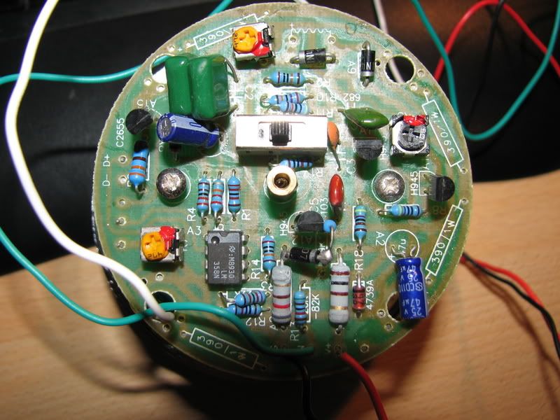
I'm still working on my body and my chassis and engine are waiting for there treatment, so I can't test it in short time, but any information is more than welcome, so I know what to do when it's time to mount the tacho. |
|
| Back to top |
|
|
Jasu
Dropped
Joined: 30 Sep 2007
Posts: 211
Location: Finland
|
| Posted: Sat Dec 08, 2007 11:02 pm Post subject: |
|
|
| phoskam wrote: | | ... also there are 3 trimmers, maybe one for each setting (4,6 and8 cilinder adjustment)... |
Maybe. It's very easy to chec it, if there is "line" from resistor to trimmer, then they are for that. Or take photo from the other side of PCB and put it here, then I can be sure of that...
I think that You can find the meaning of these trimmers by Yourself, it's as easy as it was to find right resistors there..! 
_________________
Make it today, tomorrow it's probably illegal... |
|
| Back to top |
|
|
dyanut
Dropped
Joined: 05 Aug 2007
Posts: 177
Location: North Yorkshire
|
| Posted: Thu Sep 25, 2008 10:39 pm Post subject: |
|
|
Hi Jasu,
is there any chance of advising me what the value is of that extra resistor which you used to recalibrate your Yazaki tacho for 2 cylinders?
We've got two of these to play with, but it's very difficult to figure out the colours on the 6 band resistor which is shown on your picture.
I'm wary of fitting the wrong value, when it could be 'goodnight old tacho'... 
Thanks, Ken. |
|
| Back to top |
|
|
Jasu
Dropped
Joined: 30 Sep 2007
Posts: 211
Location: Finland
|
| Posted: Fri Sep 26, 2008 11:17 am Post subject: |
|
|
| dyanut wrote: | Hi Jasu,
is there any chance of advising me what the value is of that extra resistor which you used to recalibrate your Yazaki tacho for 2 cylinders?
|
10 kilo ohms. It's good for this old Yazaki...
_________________
Make it today, tomorrow it's probably illegal... |
|
| Back to top |
|
|
ami8i
Snailer

Joined: 29 Oct 2007
Posts: 80
Location: Austria (Graz)
|
| Posted: Sat Oct 04, 2008 4:57 pm Post subject: |
|
|
Hello phoskam,
I'd try to make some reverse engineering, which means to draw the part of the circuit/schematics beginning at the 3 position selector (each direction).
I guess there are just a few resitors (R1, R2, R3, R9(?), R10, R11?) and caps on each track until all tracks meet at one point/potential.
Then make a table with lines called cylinder 8 6 and 4 in 1st column and each component in the next colomns. I estimate that you could find out the correct number with a little bit of math (proprotional, indirect proprtional).
The IC LM358N seems to expect a frequency. Check http://www.datasheetcatalog.org/datasheets/166/49945_DS.pdf and study the circuits at page 6/9. I guess circuit of Fig13 could suit to you.
If you have an idea which components should be changed remove them off the 8cylinder track and solder the 'calculated' components for 2 cylinders.
I do not recomend to change one of the marked trimmers before you don't know what to do (potentimeter of capacitor).
@BX sensors:
Diesel and BX14 sensors are not typical inductive sensor, just those of the 60-2 tooth wheel engines (BX16 BDY, BX19 ???)
I guess your speedometer is made for triggering by coil (minus) --> would not work with 'tiny' 5V squrae waves otherwise google for frequency doubler.
»Horst
_________________
»Ami8i Break http://megasquirt-de.serviceline.ch/success/index0001.htm
» BX14E.CO.2 Cruiser Break |
|
| Back to top |
|
|
|


